The contents on this page remain on our website for informational purposes only.
Content on this page will not be reviewed or updated.
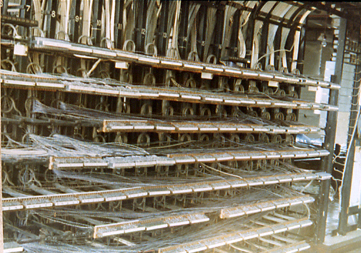
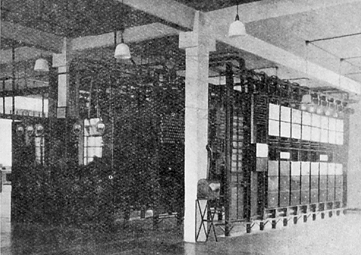
Fenny Stratford Repeater Station

Apparatus Room

The Apparatus Room was on the first floor. It was here that all the underground cables were brought in and terminated onto racks equipped with trunk test tablets. These had removable links which enabled the cable pairs to be disconnected from the repeater equipment in order to allow testing to be carried out. The test tablets were cabled away to the primaries of the line transformers and the secondaries of these were cabled to the repeater distribution frame (RDF). The RDF provided a flexibility point which allowed any cable pair to be cross-connected to the repeaters and other equipment as required.

View of Repeater Distribution Frame (RDF). General view of repeater racks in apparatus room.
View of Repeater Distribution Frame (RDF)
General view of repeater racks in apparatus room.

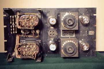
The repeaters and other associated equipment were built on standard 19'' panels and mounted on 10'6'' high racks, the bottom of which were embedded in concrete. A maximum of five repeaters could be accommodated on a rack. Also mounted on each rack was a jack field to enable the circuits passing through the repeaters to be intercepted so that monitoring and measuring of levels could be carried out. Panels equipped with fuses in the relevant supplies were also mounted above the jack field. Some racks were also fitted with volt meters and ammeters to enable the checking of the high and low tension supplies. All the repeater apparatus was supplied and installed by the Western Electric Company.

Front view of a Repeater Panel. Built on a 19'' x 10.5'' steel panel, each repeater weighed 50lbs. It shows the typical construction of the equipment at that time. The maximum gain of this example of a repeater is 42db. Gain adjustment was achieved by altering the position of the grid tap on the input transformer secondary winding. This gave coarse adjustment of around 5db per tap. Whilst fine adjustment was achieved by altering the grid tap on the inter stage transformer, these taps were wired out to a large rotary stud switch. This gave an adjustment of 1db per tap. Rear view of a Repeater Panel. Wiring was carried out using cotton-covered enamelled copper wire. The output of the repeaters would not have been adjusted to give more than +10db. For example, with an input of -32db, and with the repeater set to maximum gain, the output would be +10db. High output levels would give cross-talk problems on the cables.
Front view of a Repeater Panel. Built on a 19'' x 10.5'' steel panel, each repeater weighed 50lbs. It shows the typical construction of the equipment at that time. The maximum gain of this example of a repeater is 42db. Gain adjustment was achieved by altering the position of the grid tap on the input transformer secondary winding. This gave coarse adjustment of around 5db per tap. Whilst fine adjustment was achieved by altering the grid tap on the inter stage transformer, these taps were wired out to a large rotary stud switch. This gave an adjustment of 1db per tap.
Rear view of a Repeater Panel. Wiring was carried out using cotton-covered enamelled copper wire. The output of the repeaters would not have been adjusted to give more than +10db. For example, with an input of -32db, and with the repeater set to maximum gain, the output would be +10db. High output levels would give cross-talk problems on the cables.

Home | What are Repeaters? | Early Years | Power Room | Battery Room | The War Years | The Decline | The Defence Teleprinter Network
Bletchley Park Homepage | Bletchley Park Jewels Home Page | Telecom Heritage Group | Telegraph Museum, Porthcurno | Connected Earth | The Telephone Museum